3 Wire Single Phase Submersible Pump Wiring Diagram

Vt Commodore Ignition Wiring Diagram, Complete Wiring Diagrams For Holden Commodore VT, VX, VY, VZ, VE, VF, 5.36 MB, 03:54, 32,796, John Amahle, 2018-08-01T19:37:41.000000Z, 19, Vt Commodore Ignition Wiring Diagram, to-ja-to-ty-to-my-to-nasz-swiat.blogspot.com, 1272 x 1800, jpeg, bcm pcm 12j swiat nasz, 20, vt-commodore-ignition-wiring-diagram, Anime Arts
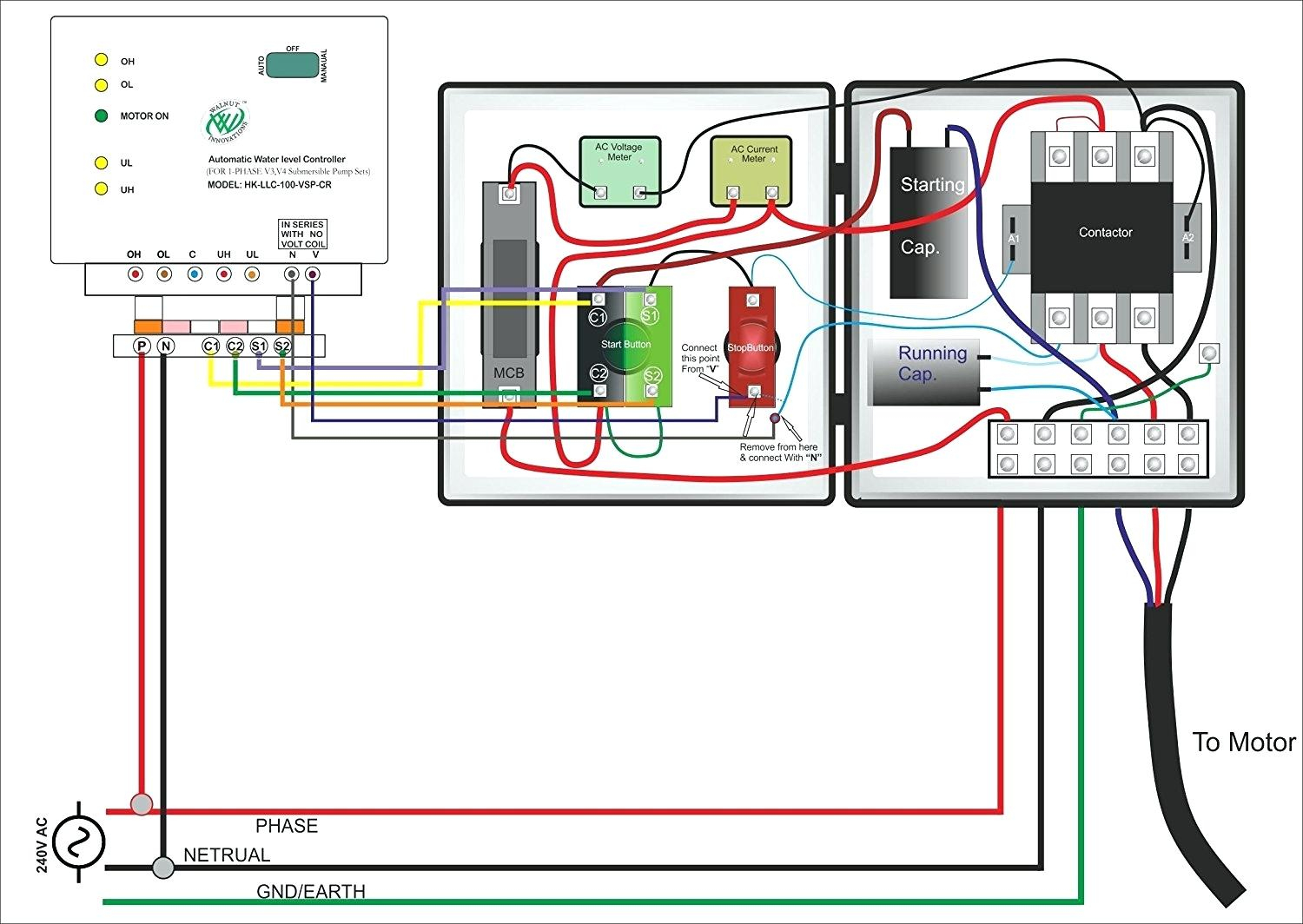
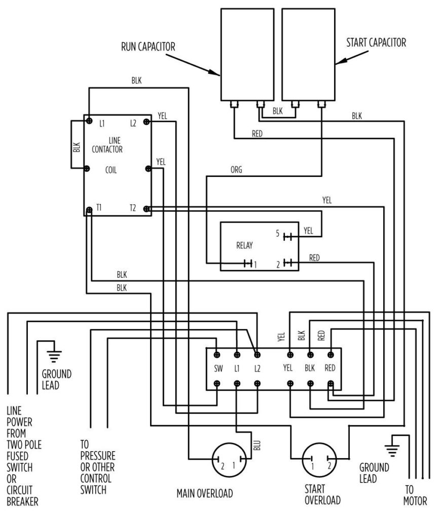
Submersible pump wiring diagram. Great single phase starter wiring diagram a big compressor throughout. Wiring diagram valve port nest honeywell plan heating central motorised system electrical diy water diynot data today safety systems neutral. Automatic starter for submersible pump.
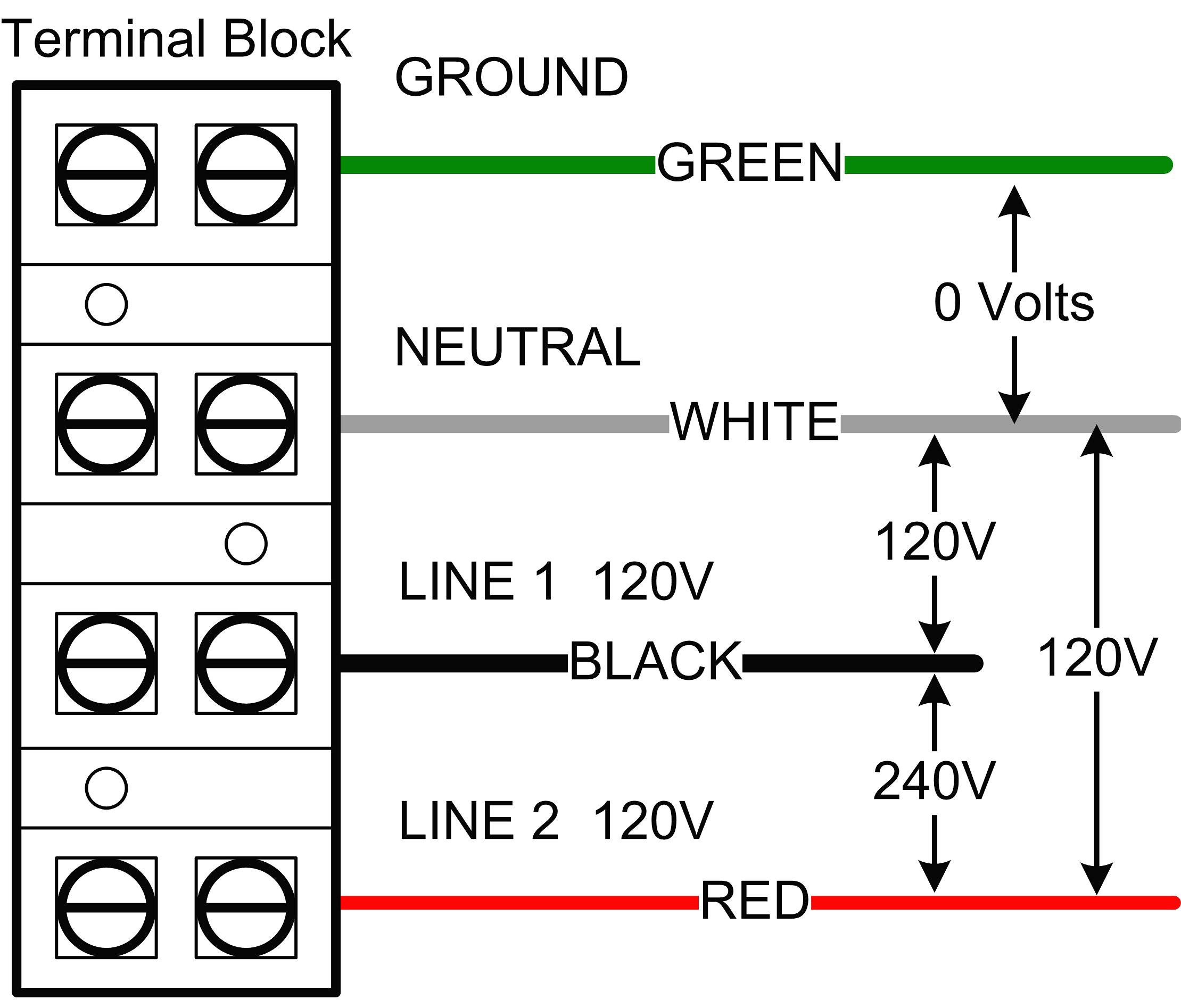
Disconnection of the motor wires. Honeywell thermostat wiring diagram 3 wire. Great single phase starter wiring diagram a big compressor throughout. 5 wire ceiling fan capacitor wiring diagram. First, see the 3 phase submersible pump wiring diagram and after that, i will explain each step of the below. Submersible pump control box wiring diagram for 3 wire single phase. Submersible pump control box wiring diagram for 3 wire single phase. Old fashioned single phase submersible motor starter wiring diagram. In this video i go over the differences of a 2 wire and a 3 wire submersible well pumpthis is associated with the starting components for.
3 Wire Submersible Pump Wiring Diagram | Wiring Diagram

Submersible Pump Control Box Wiring Diagram For 3 Wire Single Phase | Electrical Online 4u

3 Wire Submersible Pump Wiring Diagram - Cadician's Blog

3 Wire Well Pump Wiring Diagram | Wiring Diagram

3 Wire Submersible Pump Wiring Diagram - Cadician's Blog

Submersible Pump Control Box Wiring Diagram For 3 Wire Single Phase - Style Guru: Fashion, Glitz

3 Wire Submersible Pump Wiring Diagram - Diagram Stream

35+ Trends For Single Phase Submersible Pump Starter Wiring Diagram Pdf - Ralf Hirsch

3 Wire Submersible Pump Wiring Diagram
3 Wire Well Pump Wiring Diagram : Diagram 2wire Well Pump Wiring 115v Diagram Full Version Hd
